
Hydraulic manifold deburring is especially challenging when burrs form at drilled passage intersections and cross-holes. If left uncontrolled, burrs and loose particles can contribute to contamination, interfere with small flow passages, and make hydraulic cleanliness requirements more difficult to achieve. Because many of these features are located deep inside the manifold, conventional hand tools and visual inspection may not reach every critical edge.
The right deburring method depends on the internal geometry, material, burr size, required edge condition, surface finish, cleanliness requirements, and production volume. Mechanical deburring may be suitable for accessible features, while complex internal passages may require processes such as abrasive flow machining, thermal deburring, or other controlled finishing methods. This guide explains how to evaluate these options for precision hydraulic manifolds.
Key Takeways
- Burrs commonly form at intersecting drilled holes and cross-passages inside hydraulic manifolds.
- The deburring process should be selected according to geometry, burr condition, edge requirements, and production volume.
- Abrasive flow machining can reach complex internal passages and can be used for deburring, edge radiusing, and surface finishing when the application is suitable.
- Cleaning and inspection after deburring are important for controlling residual particles and confirming the condition of internal features.
Why Internal Burrs Matter in Hydraulic Manifolds
Hydraulic manifolds contain networks of drilled holes, cross-passages, valve cavities, and threaded ports that direct fluid through the system. During drilling and machining, burrs can form where these features intersect. Unlike external burrs, internal burrs may be difficult to see and difficult to reach with conventional tools.
If an internal burr remains partially attached, it can break loose during assembly or operation and become a source of particulate contamination. Burrs can also interfere with small flow passages, sealing areas, valve movement, and cleanliness requirements. For this reason, internal deburring should be treated as part of the functional manufacturing process rather than only as a cosmetic finishing operation.
Typical Locations Where Burrs Form
- Intersections between two drilled passages
- Cross-holes and intersecting bores
- Entry and exit edges of drilled holes
- Valve cavities and internal shoulders
- Threaded ports and machined internal features
Methods for Deburring Internal Passages
No single deburring process is suitable for every hydraulic manifold. The best method depends on whether the burr is accessible, the complexity of the internal passages, the required edge condition, the material, dimensional sensitivity, and production volume. In many projects, more than one deburring or finishing process may be used to achieve the required result.
Mechanical Deburring
Mechanical deburring uses tools such as brushes, abrasive stones, rotary tools, scrapers, or specialized cross-hole deburring tools to remove burrs from accessible features. It is often practical for external edges, open bores, and internal features that can be reached directly.
The main limitation is accessibility. Deep intersections, curved passages, and complex internal channels may be difficult to reach consistently. Manual processing can also introduce variation between operators, so the method is better suited to features that can be clearly accessed, controlled, and inspected.
- Best for accessible holes and edges
- Relatively simple and flexible
- Suitable for prototypes and lower production volumes
- Limited access to deep or complex internal passages
- Process consistency may depend on tooling and operator control
Abrasive Flow Machining (AFM)
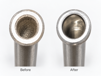
Abrasive flow machining uses a controlled abrasive media that is forced through or across selected internal features. As the media passes through restricted areas and internal intersections, it can remove burrs, smooth machining marks, radius sharp edges, and improve surface finish in areas that are difficult to reach with conventional tools.
AFM can be particularly useful for intersecting passages, internal bores, and complex flow paths, but the process must be matched to the part geometry and finishing objective. Fixture design, media characteristics, flow path, processing pressure, cycle settings, and the amount of material to be removed can all influence the final result.
- Reaches internal features that may be inaccessible to conventional tools
- Can combine deburring, edge radiusing, and surface finishing
- Suitable for complex intersecting passages
- Requires controlled tooling and process development
- Not every geometry or tolerance condition is suitable for AFM
When AFM Is a Good Fit
Abrasive flow machining is most useful when critical burrs or surface irregularities are located in internal areas that conventional tools cannot reach consistently. Typical candidates include intersecting passages, internal bores, cross-holes, and flow paths where controlled edge radiusing or surface improvement is required.
AFM should not be selected only because a feature is internal. The required material removal, dimensional tolerance, edge condition, passage geometry, and accessibility for media flow should all be evaluated before the process is specified.
- Intersecting internal passages
- Cross-holes that are difficult to reach mechanically
- Internal bores requiring surface improvement
- Components requiring controlled edge radiusing
- Repetitive parts where a consistent finishing process is needed
Thermal Deburring
Thermal deburring uses a controlled combustion process to remove small burrs from internal and external edges. Because the hot gases can reach connected internal passages, the process can be effective for burrs located at cross-holes and other difficult-to-access intersections.
The process is fast and can treat multiple burr locations in a single cycle, but it does not selectively remove material from one specific edge. Part material, geometry, wall thickness, cleanliness requirements, and the effect of heat on the component must therefore be evaluated before thermal deburring is selected.
- Can reach multiple connected internal passages
- Effective for small burrs at cross-hole intersections
- Fast processing for suitable production parts
- Does not provide the same surface-finishing effect as AFM
- Material and geometry limitations must be evaluated
Mechanical vs AFM vs Thermal Deburring
Each process solves a different manufacturing problem. Mechanical deburring is usually the simplest option when the burr can be reached directly. AFM becomes more attractive when the critical features are located deep inside complex flow paths and controlled edge or surface improvement is required. Thermal deburring can be efficient when many small burrs are distributed throughout connected passages.
| Criteria | Mechanical | AFM | Thermal |
|---|---|---|---|
| Accessible external edges | Excellent | Possible | Possible |
| Deep internal passages | Limited | Excellent | Good |
| Cross-hole burr removal | Good if accessible | Excellent | Excellent |
| Surface finish improvement | Limited | Excellent | No significant improvement |
| Process control | Tool/operator dependent | Media and parameter controlled | Process-cycle controlled |
This comparison is a general guide rather than a universal process-selection rule. Final process selection should be based on the actual drawing, material, burr condition, dimensional tolerances, internal geometry, cleanliness requirements, and production quantity.
How to Choose the Right Deburring Method
Selecting a deburring process should begin with the function of the part rather than the finishing technology itself. For hydraulic manifold deburring, the most important questions are where the burr is located, how much material can be removed, whether the edge geometry is critical, and how the internal passage will be inspected and cleaned after processing.
A process that works well for an accessible drilled hole may not be suitable for a deep cross-passage or a complex internal flow path. The drawing, material, production quantity, dimensional tolerances, cleanliness requirements, and required surface condition should therefore be reviewed together before the deburring method is finalized. For hydraulic manifold deburring projects involving difficult cross-holes or complex internal passages, send us your drawing and project requirements.
Key Factors to Review
- Burr location and accessibility
- Material and hardness
- Internal passage geometry
- Required edge condition
- Surface finish requirement
- Dimensional tolerance
- Cleanliness specification
- Production quantity and repeatability
When More Than One Process May Be Needed
Some hydraulic components require a combination of processes rather than a single deburring method. Accessible external edges may be handled mechanically, while deep internal intersections may require AFM or another controlled internal finishing process. Final cleaning can then be used to remove residual particles, abrasive media, machining oil, and other contaminants before inspection or assembly.
This combined approach is often more practical than forcing one process to solve every finishing requirement on the part.
Surface Finish and Edge Requirements
Deburring and surface finishing are related, but they are not the same requirement. Removing a burr may leave the surrounding surface essentially unchanged, while some hydraulic components also require controlled edge radiusing or an improved surface condition inside bores and flow passages.
The required result should therefore be defined on the drawing whenever possible. Engineers should distinguish between simply removing loose or attached burrs, creating a specified edge break or radius, and improving surface roughness. This helps prevent unnecessary material removal and makes the finishing process easier to control.
Surface Roughness vs. Edge Radiusing
Surface roughness describes the texture of a machined surface, while edge radiusing describes the geometry created at a sharp edge or intersection. A process may improve one without necessarily achieving the required result for the other.
For example, abrasive flow machining can be used to remove small burrs, smooth internal surfaces, and create controlled edge radiusing in suitable applications. However, the amount of material removed and the final edge condition depend on the geometry, media flow, tooling, and process parameters, so the target condition should be agreed before production.
Why Cleanliness Requirements Matter
Deburring is only one step in preparing a hydraulic manifold for assembly. Burr fragments, abrasive residue, machining chips, oil, and other particles can remain inside internal passages after machining and finishing. These contaminants should be removed through an appropriate cleaning process before final inspection or assembly.
The required cleanliness level depends on the hydraulic system and the sensitivity of the downstream components. For this reason, customers should provide any applicable cleanliness specification together with the drawing and other finishing requirements.
Cleaning After Deburring
After deburring or internal finishing, the component should be cleaned to remove loose burr fragments, abrasive residue, machining chips, oil, and other contaminants from internal passages. This step is particularly important for hydraulic components because small particles can remain trapped in cross-holes, blind passages, threaded ports, and complex internal cavities.
The cleaning process should be selected according to the part geometry, contamination type, material, and required cleanliness level. Depending on the application, cleaning may include flushing, high-pressure cleaning, ultrasonic cleaning, aqueous cleaning, air blow-off, drying, or a combination of several methods.
Cleaning Considerations for Internal Passages
- Remove loose particles and residual abrasive media
- Flush cross-holes and blind passages thoroughly
- Confirm that cleaning fluid can reach critical internal areas
- Prevent secondary contamination during drying and handling
- Follow any customer-specified cleanliness requirement
Inspection and Verification
Internal deburring should be verified whenever the burr location or edge condition is functionally important. Visual inspection may be sufficient for accessible features, but deep internal passages can require additional inspection methods to confirm that burrs have been removed without excessive material removal.
Depending on the component and specification, verification may include borescope inspection, dimensional measurement, surface roughness measurement, edge-radius checks, cleanliness testing, or functional inspection. The inspection method should be defined according to the drawing and the risk associated with the internal feature.
What Should Be Verified?
- Burr removal at critical intersections
- Edge condition or specified radius
- Dimensional integrity of finished features
- Surface condition where required
- Residual contamination after cleaning
- Consistency across production parts
What to Include in an RFQ for Hydraulic Manifold Deburring
Providing complete technical information at the RFQ stage makes it easier to evaluate the appropriate deburring, finishing, and cleaning process. For complex internal passages, the drawing alone may not always show which intersections are functionally critical.
When possible, include the information below so the manufacturing and finishing process can be reviewed before production.
- 2D drawing and 3D model
- Part material
- Annual or batch quantity
- Locations where burr removal is required
- Edge break or radius requirements
- Surface roughness requirements
- Critical dimensional tolerances
- Cleanliness specification
- Inspection requirements
- Photos or samples of existing burr conditions, if available
Need Help with a Hydraulic Manifold Project?
QilTroon supports precision machining, internal deburring, abrasive flow machining, cleaning, and related post-processing for hydraulic and other precision components.
If your project includes difficult cross-hole burrs, complex internal passages, surface-finishing requirements, or cleanliness specifications, send us your drawing and project requirements. We can review the geometry and help evaluate a suitable manufacturing and post-processing route.